TL;DR
- This blog is for engineering students, technology learners, and freshers who want to understand BLDC motors clearly from basic concept to real-world application, without prior background in electrical machines.
- The full form of BLDC motor is Brushless DC Motor and removal of mechanical brushes is a single design change that defines everything about its superior performance.
- Electronic commutation using Hall effect sensors or back-EMF detection replaces the role of brushes, giving motor precise rotor position awareness and smooth, efficient switching.
- BLDC motors outperform brushed DC motors in efficiency, lifespan, and noise levels which is why they are found in electric vehicles, drones, robotics, and consumer appliances worldwide.
- Understanding BLDC motors is foundational for anyone entering fields of embedded systems, motor control, electric vehicles, or industrial automation.
Introduction
The electric motor is one of the basic components in modern engineering. Motors convert electrical energy into mechanical motion, ranging from fan cooling a notebook computer to powering an electric vehicle. Brushed DC motors were the most common motors used in low-power or variable-speed applications for much of the twentieth century. Simple, cost-effective, and well-known, but with the inherent limitation of using mechanical brushes.
Brushes wear down. They create friction. They produce electric noise. They restrict top speed and performance of the motor. But with the advent of reliable power electronics and microcontrollers, many of these compromises have been significantly reduced.
To overcome these limitations, BLDC Motor (Brushless DC Motor) was born. The BLDC motor eliminated the root cause of the most performance and durability problems in brushed motors by replacing the mechanical commutation system with an electronic one. Today, BLDC motors are among the most widely used motor types in the world, found in applications ranging from consumer electronics to aircraft systems.
This guide offers a step-by-step introduction to BLDC motors, covering their full form, construction, working principle, commutation methods, types, advantages, limitations, and applications.
Also Read,
- Components of an Electric Vehicle – A Beginner’s Guide
- Working Principle of Electric Vehicle: A Complete Beginner’s Guide
- Top Microwave Experiments Every Electronics and Communication Student
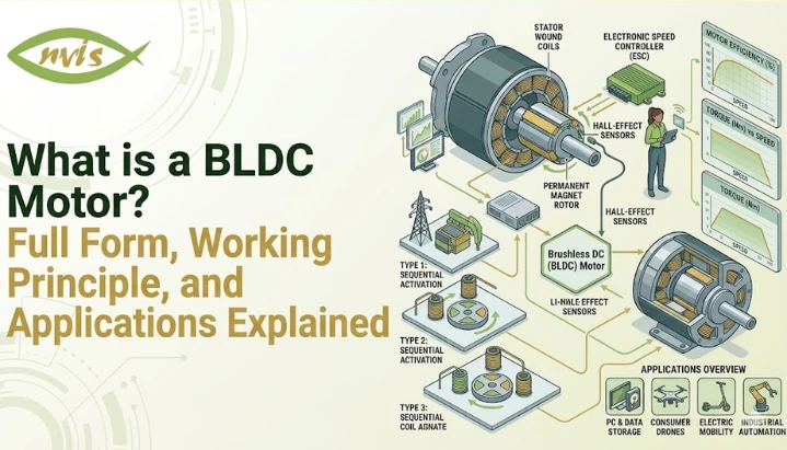
What is a BLDC Motor?
A BLDC motor (Brushless DC Motor) is an Electronic Commutated Electric Motor that uses direct current and has no mechanical brushes and commutator.
In a typical brushed DC motor, the current is conducted to the windings of the rotor through a rotating commutator ring with the assistance of carbon brushes. This contact allows current to flow through the rotor windings, producing a magnetic field that causes rotation. It is a working system, but using physical contact between brushes and commutators causes friction, heat, wear and sparking – all of which affect the performance and lifespan of the system over time.
In contrast, a BLDC motor uses a different construction and commutation method. The rotor is made of permanent magnets and the stator has stationary copper windings. Current switching to the stator windings is more precisely controlled in sequence using an electronic controller instead of a mechanical brush-commutator pair. The electronically controlled switching generates a rotating magnetic field that is acted upon by the permanent magnets in the rotor to generate the rotation.
The outcome is a motor without physical contact between rotating and stationary components in the electrical circuit, eliminating the primary cause of wear and energy loss of brushed motors.
BLDC Motor Full Form
The full form of the BLDC motor is Brushless DC Motor. Each word in this name carries technical meaning:
- A brushless motor operates without mechanical carbon brushes. Commutation is handled electronically.
- The DC motor is powered by direct current. Internally, the electronic controller converts this into sequenced AC signals to drive stator windings.
- A motor machine converts electrical energy into mechanical rotational energy.
It is important to note that although BLDC stands for Brushless DC Motor, its stator windings are energized using electronically switched AC waveforms. The motor is operated from a direct current source, but the windings in its stators are driven by alternating currents which are switched in sequence by an electronic controller. In motor engineering, a BLDC motor is considered a DC motor because it operates from a DC supply, even though its stator windings are driven by electronically switched AC waveforms.
Construction of a BLDC Motor
A BLDC motor consists of three principal components: stator, rotor, and electronic controller.
Stator
A stator is a fixed outer structure of a motor. It is equipped with three-phase copper winding on a laminated steel core. When energized in a certain order, this creates a rotating magnetic field within the motor. The structure of the stator of a BLDC motor is much like that of an AC induction motor or a PMSM motor.
The number of the stator poles affects the torque characteristic and the speed range of the motor. The more poles there are, the smoother the torque at low speeds.
Rotor
The rotor is the rotating part of the motor. The BLDC motor’s rotor is also equipped with permanent magnets, unlike brushed DC motors that feature windings on the rotor. The magnets are usually constructed from high energy rare earth materials like Neodymium Iron Boron (NdFeB) which offer a powerful magnetic field within a small space.
Alternating north-south pole pairs of permanent magnets are placed around the rotor. The rotor magnets align with and follow the rotating magnetic field created by the stator, causing the rotor to rotate.
Electronic Controller
Unlike all mechanically commutated motors, a BLDC motor system is controlled using an electronic controller. The controller performs the same commutation function that brushes and a commutator perform in a brushed DC motor, but electronically and without any physical contact.
The controller continually samples the rotor position either by sensors or by indirect methods and automatically switches the current in the three phases of the stator in the right sequence at the right time. This exact electronic switching is referred to as commutation, and is the essence of BLDC motor operation.
How Does a BLDC Motor Work?
The process of a BLDC motor operates on the principle of the interaction between the rotating magnetic field produced by the stator and the magnetic field of the permanent-magnet rotor.
When stator phases are energized in sequence, they create a rotating magnetic field. The permanent magnets on the rotor continuously align with this field, producing rotation in the rotor toward the energized phase. Once the rotor aligns with that magnetic field, the controller will change the current to the next phase. The new field continues to be followed by the rotating rotor. The next stage is then energised and the rotor follows once more.
By continuously switching current between the three phases of the stator, the effect is that of a rotating magnetic field, and the rotor follows the rotating magnetic field continuously, thus achieving smooth rotation.
The timing of the switching sequence needs to be accurate to the rotor’s true position. If switching occurs too early or too late, the torque output will decrease and the motor may lose synchronisation. That is why rotor position feedback is so important to the operation of BLDC motors.
The idea of timing requirements is similar to that of a relay race: imagine it’s a relay. The runners do not retrieve the baton at the proper times: too early or too late and the team loses its advantage. The BLDC controller does the same switching between the stator phases and uses the position of the rotors as a timing reference.
Commutation Methods in BLDC Motors
Commutation refers to the process of determining when and how to switch current between stator phases. In a BLDC motor, this is done electronically using one of two primary methods.
Sensored Commutation Hall Effect Sensors
Hall effect sensors embedded in the stator are commonly used to detect rotor position in most BLDC motors found in servo, robotics and EV applications. Three Hall sensors are typically spaced 120 electrical degrees apart. The permanent magnets, as they pass each sensor, trigger a position signal as the rotor rotates. These three signals are used by the controller to calculate the rotor position correctly with sufficient accuracy, which in turn is used to time the commutation.
Hall sensor based commutation is reliable, gives accurate position feedback at low velocity and has a smooth motor start-up. The downside is that extra wiring, additional hardware, possible failure points and increased cost.
Sensorless Commutation Back-EMF Detection
As the rotor rotates, a voltage is induced in the stator winding that is not currently energized. This voltage created is known as the back-EMF or back electro-motive force. This back EMF can be sensed by the controller during the non-active phase, and it can be used to determine the position of the rotor without using any physical sensor.
The drawback of the sensorless commutation is that the back-EMF is proportional to the rotor speed at very low speeds or standstill, making the measurement unreliable. This means that sensorless BLDC motors are not as well suited for applications that demand smooth low-speed or zero-speed operation.
Types of BLDC Motors
BLDC motors are classified based on their physical rotor-stator configuration.
Inrunner BLDC Motor
In an inrunner BLDC motor, the conventional arrangement for most electric motors is having a permanent magnet rotor inside stator windings. Inrunner motors have a compact rotor geometry and are typically used in drones, RC aircraft, and/or high-speed industrial spindles where they can achieve high rotational speeds in a short amount of time.
Outrunner BLDC Motor
The rotor is placed outside of the stator in an outrunner BLDC motor, with permanent magnets attached to the rotating outer housing surrounding the inner stator coils. The outrunner configuration will, of course, generate more torque at lower speeds which is the reason why this type is used in applications such as drone propellers, camera gimbals, and e-bikes wheel hubs.
Advantages of BLDC Motors
The change from brushed to brushless motor design is a set of consistent but significant benefits.
Higher Efficiency: BLDC motors convert more of the electricity into mechanical energy since there is no friction in the brushes, no electrical loss in the commutator. Typical efficiencies are higher, at 85-90%, than the 75-80% for comparable brushed motors.
Eliminating brushes removes the primary source of wear in DC motors, significantly extending operational lifespan in DC motors. The BLDC motors can run for tens of thousands of hours with little maintenance, suitable for embedded and continuous duty applications.
In brushed DC motors, arcing between the brushes and commutator generates electrical noise and electromagnetic interference (EMI). BLDC motors generate significantly less electrical noise, particularly important in precision electronics, medical equipment, and communication devices.
An electronic controller for the BLDC motor system can control speed and torque by high precision within a wide range of operation. This makes BLDC motors ideal for situations where repeatable and controlled motion is needed.
High Power Density: BLDC motors deliver high power output in a compact and lightweight form factor in a small space and lighter weight. This small form factor power delivery is especially beneficial when space and portability are limited, like in wearables, handheld tools and drones.
Low Maintenance: BLDC motor systems need much less periodic maintenance than brushed motors as they do not require brushes to be inspected or replaced. This minimizes downtime and operating expenses for industrial and commercial applications.
Limitations of BLDC Motors
Although BLDC motors have some benefits, there are also some engineering issues to consider when designing with BLDC motors.
The initial cost of a BLDC motor system is generally higher than that of brushed motor alternatives as these systems include both rare-earth permanent magnets and drive electronics.
Control Complexity: A BLDC motor can’t simply be connected directly to a DC power supply and operated. It needs a special electronic drive system for commutation, timing and protection. This makes the design more complex and puts demands on embedded control software.
In the case of motors with trapezoidal commutation with Hall sensors, there may be small torque variations between the phases called torque ripple. This is manageable in many applications but in precision positioning applications where smooth torque delivery is crucial this can be a problem.
Low-Speed Performance with Sensorless Control – Sensorless BLDC motor systems with back-EMF detection are incapable of performing well at very low speeds due to the low level of back-EMF signals at this speed. If fine low speed control is required, sensored systems or more advanced control algorithms are required.
Applications of BLDC Motors
This combination of high efficiency, small size, long life and controllability makes BLDC motor the standard choice in a wide variety of modern technologies.
Electric Vehicles and E-Mobility
BLDC motors are widely used in electric bicycles, electric scooters, and various auxiliary systems in electric vehicles. Some EV traction systems also use permanent-magnet motor technologies closely related to BLDC designs. These motors are highly efficient and reliable under variable load conditions and are suitable for personal electric mobility applications.
Drones and UAVs
Drones and Unmanned Aerial Vehicles (UAVs) are generally equipped with Outrunner BLDC motors. A high power-to-weight ratio, precise speed control, and quick throttle input response are crucial for stable and agile flight.
Robotics and Industrial Automation
BLDC motors are used in precision, reliability and low maintenance applications like robotic joints, conveyor systems and automated guided vehicles (AGVs). In manufacturing applications, having precise speed control with variable loads becomes very useful.
Consumer Appliances
BLDC motors are commonly used to power washing machines, air conditioner compressors, cooling fans of computers and servers for their energy saving properties and low noise emission. Energy efficient BLDC fan motors are widely used in residential and commercial buildings in India owing to the BEE star ratings encouraging the use of less energy in ceiling fans.
HVAC Systems
The advantages of BLDC motor technology to HVAC Systems (Heating Ventilation Air conditioning) are variable speed operation, saving energy, and increasing service life of the compressor & blower fan.
Medical Equipment
BLDC motors provide quiet, precise, and reliable actuation in medical equipment , including infusion pumps, surgical tools, prosthetics, and respiratory equipment. BLDC motors are consistent in fulfilling these requirements.
Aerospace Systems
For flight control surfaces, fuel pumps and auxiliary power systems in aircraft, reliability and power density are important design factors for BLDC motors.
BLDC Motor vs Brushed DC Motor
When the learner has prior knowledge with DC motors, a direct comparison helps him understand the significance of the brushless design.
A brushed DC motor has a commutator that rotates and has carbon brushes in contact with it that conduct the current to the windings on the rotor. Commutation is always by contact, and in turn, is limited because the brushes wear away over time. Friction, heat, and electrical noise are all created when touching the object. Mechanical limitations of commutator assembly limit the maximum operating speeds.
All of this is avoided in a BLDC motor by moving the windings to the stator and replacing mechanical commutation with electronic switching. The rotor is the only component that contains permanent magnets and there is no component that wears out in the electrical circuit. The speed limit depends upon the magnetic and thermal design of the motor and NOT mechanical contacting limits. This makes the system more efficient since there are no losses due to friction or commutation.
The disadvantage of this is that a BLDC motor must be operated by an electronic controller. A brushed motor can be operated by just applying a voltage. The BLDC motor needs to be driven by a properly sequenced drive system that adds complexity and cost to the design, but also allows for much greater optimization of motor performance.
BLDC Motor vs PMSM Motor
BLDC motors are commonly used along with PMSM motors (Permanent Magnet Synchronous Motor) in similar application scenarios. The difference is that both are equipped with permanent magnet rotors and electronic controllers.
The main technical difference is related to the back-EMF waveform and commutation strategy:
The BLDC motor generates trapezoidal back-EMF and is generally operated using square-wave current switching. This is more easily done, but results in some torque ripple from commutation steps.
A PMSM motor produces sinusoidal back-EMF and is typically driven using advanced sinusoidal current control methods such as Field-Oriented Control (FOC). This results in smoother torque and less ripple, but more complicated control electronics.
BLDC motors are also commonly used in practical engineering applications where they need to be simple, inexpensive, and reasonably performative such as in fans, pumps and general-purpose drives. PMSM motors are well suited for applications that demand precise and quiet motor torque in a broad speed range, such as servo drives, electric vehicles (EVs) and precision motion systems.
Conclusion
BLDC motor is a new generation of electric motor. In most applications, BLDC motors offer significantly higher efficiency, longer service life, and better controllability than brushed motor technologies, by replacing mechanical brushes and commutators with an electronic control system and moving windings to the stator.
Drone propulsion systems, EV powertrains, home appliances, and medical devices are just a few examples of the numerous technologies where BLDC motors play a crucial role in modern engineering. Beyond performance benefits, their increased use is due to greater industry trends in intelligent control, energy saving, and electrification.
The study of BLDC motor, its acronym and working principle, commutation and its applications will help engineering students and technology learners to have a solid understanding of the BLDC motor which will help them in motor control, embedded systems, electric mobility and industrial automation work.
FAQs
The full form of the BLDC motor is the Brushless DC Motor. It is a type of DC-powered electric motor, where the mechanical brushes and commutators have been replaced with an electronic controller that controls the current switching of the motor’s stators.
As in an ordinary brushed DC motor, current is transferred to the windings on the rotor via the carbon brushes in contact with a rotating commutator. A BLDC motor gets rid of this contact altogether, with windings on the stationary stator, and permanent magnets on the rotor. It uses an electronic controller that eliminates friction, wear and electrical noise by eliminating brushes.
The position of the permanent magnet rotor is detected by hall effect sensors detecting the change in magnetic field. This positional information is used by an electronic controller to sequence and time the energisation of stators. The accurate feedback of rotor position is crucial for smooth commutation and efficient torque generation.
While a brushed DC motor can be put into operation by applying a voltage, the BLDC motor needs to be controlled by an electronic controller.The controller energizes the stator phases in the correct sequence to generate a rotating magnetic field that the rotor follows. It is required to switch the stator phases in the correct sequence and produce the rotating magnetic field needed for rotor motion.
Sensored BLDC motors have Hall sensors installed within the stator to directly sense the rotor’s position. This ensures safe commutation at any speed, even at low speeds and standing operation. In Sensorless BLDC motors, rotor position is determined by measuring the back-EMF on an unenergized stator phase. This not only saves on cost and complexity but is also less effective at very low speeds because back-EMF signals are very low at such speeds, making accurate measurement difficult.
The motors are both permanent magnets and have a different back-emf characteristic; they also use electronic controllers but with different control strategies. The BLDC motor generates trapezoidal back-EMF while its square-wave commutation is easier to accomplish than sine-wave, but generates some torque ripple. A PMSM motor generates sinusoidal back-EMF, and employs sinusoidal current control like Field Oriented Control, which makes the motor produce smoother torque and lower noise, but at the expense of the electronics.